Welcome to another exciting tutorial from Aaenics
Still on the linear electronics series, and if you’ve been following for a couple of weeks now, you’ll know we’ve been having a hands-on journey into basic electronics components and how they work together.
Today in this simple but powerful tutorial, we’re going to learn what an LED resistor switch circuit is, how it works, and how to actually build one by yourself with just a few components.
What is an LED Resistor Switch Circuit
An LED resistor switch circuit is one of the most basic and fundamental circuits you’ll ever build in electronics. It combines three simple components, an LED (Light Emitting Diode), a resistor, and a switch, and teaches you core principles like current limiting, switching control, and polarity.
The idea is very simple:
You press the switch,
Current flows through the resistor,
The resistor limits how much current gets to the LED,
And the LED lights up
But behind this simplicity lies a beautiful lesson about how electronic circuits control and manage electrical energy.
How Does It Work
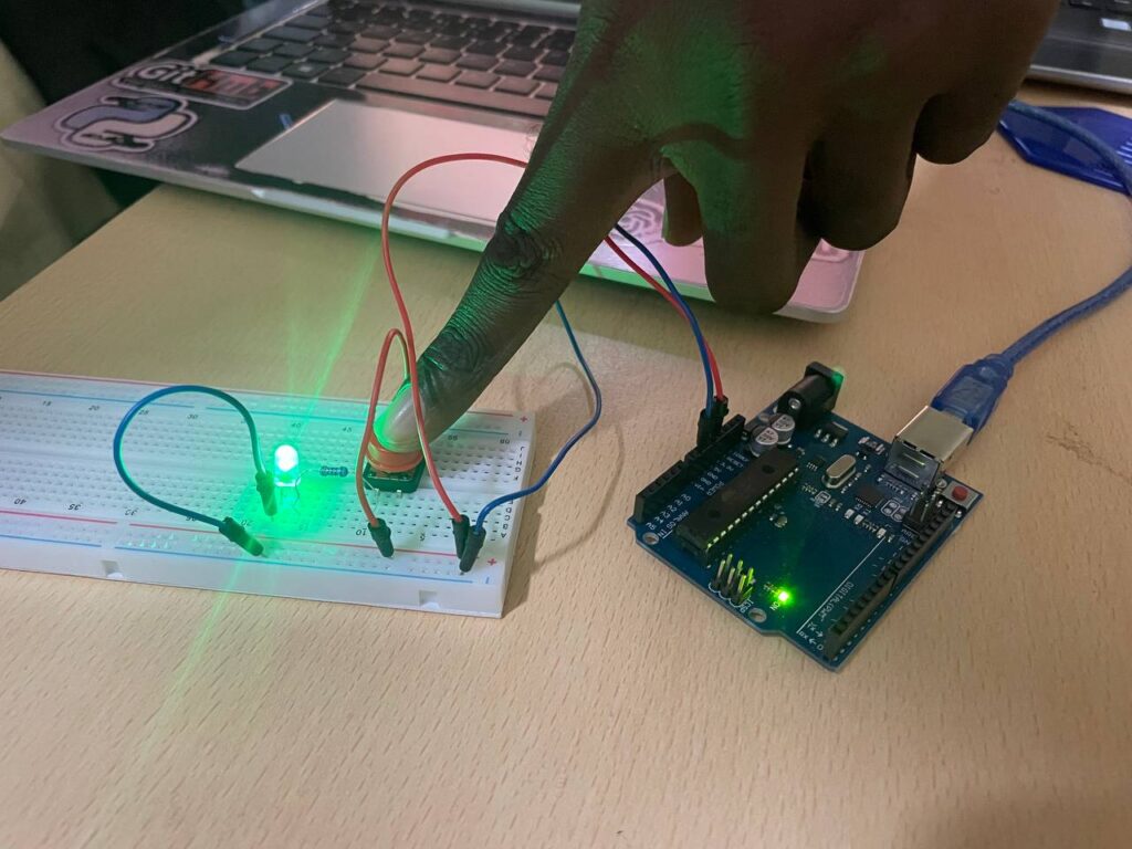
Let’s say we are powering the circuit with a 5V source like an Arduino or a battery. The switch acts like a gate. When it’s open, the current can’t pass through so the LED stays off. When you press the switch, the gate closes and current flows.
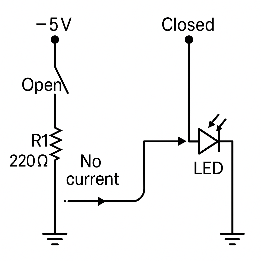
But wait, without the resistor, you could burn your LED in seconds. That’s why the resistor is crucial. It limits the amount of current flowing through the LED so it stays safe and shines properly.
Think of the resistor as a kind of bodyguard for your LED. It absorbs just enough energy so the LED can do its job without overheating.
Let’s Build It
So, how do you actually build this thing? Here’s what you need:
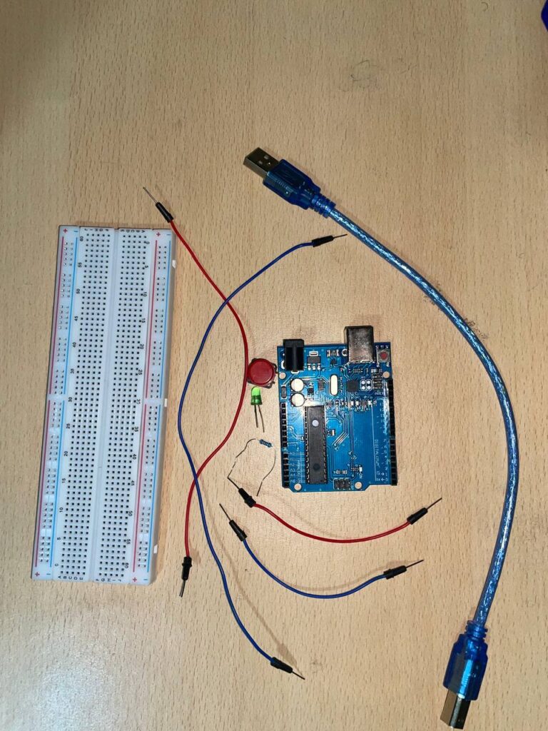
Components
1 LED (any color)
1 resistor (220Ω to 1kΩ is fine)
1 push button switch
Breadboard and jumper wires
Power supply (e.g. Arduino 5V or 9V battery)
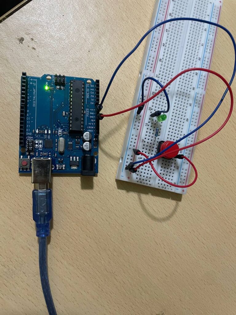
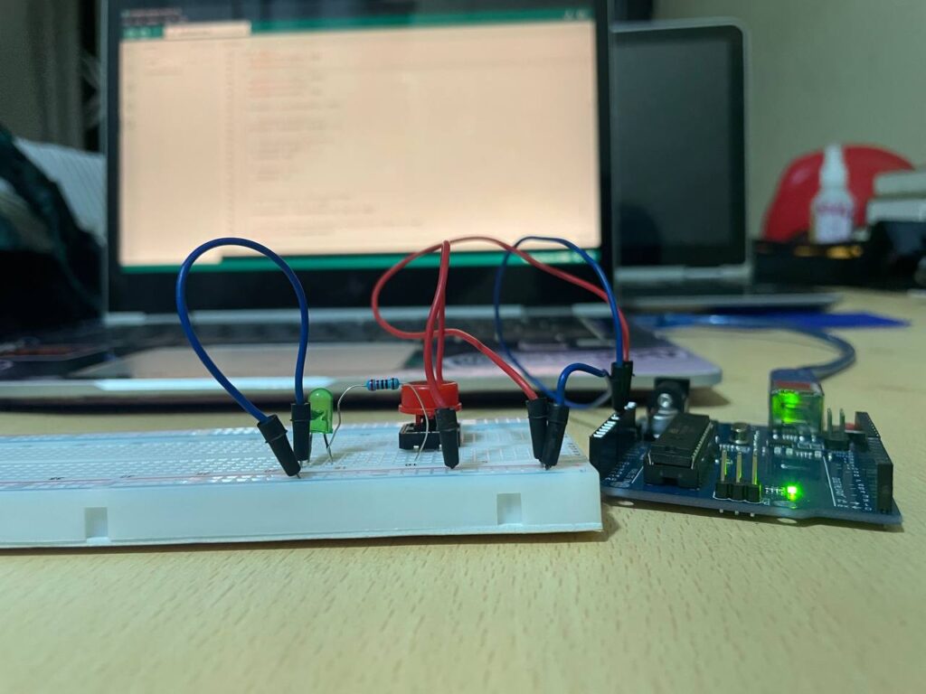
Connections
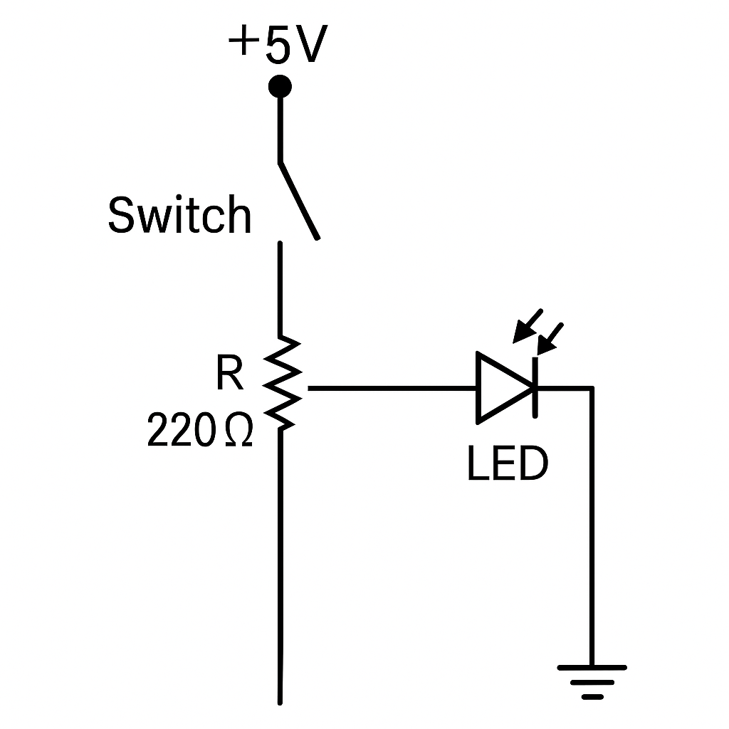
1. Connect one terminal of the switch to the positive voltage
2. Connect the other terminal of the switch to one end of the resistor
3. Connect the other end of the resistor to the anode (longer leg) of the LED
4. Connect the cathode (shorter leg) of the LED to GND
5. That’s it. Press the switch and your LED comes alive
What You’ve Learned
Switches are simple but powerful control elements in a circuit
LEDs only allow current in one direction and glow when current passes
Resistors are current limiting devices that protect sensitive components
Putting them together teaches you the basics of flow control in circuits, which is a big deal in real world electronics
So go ahead, build this circuit and light up your electronics journey
Stay tuned for more awesome lessons here at Aaenics