The NE555 Timer IC is one of the most popular and versatile integrated circuits in electronics. It operates in three distinct modes—astable, bistable, and monostable—making it perfect for building simple yet powerful timer-based circuits.
In this article, we will explore three basic yet exciting projects using the NE555:
- Astable Mode – functions as a continuous oscillator or pulse generator.
- Bistable Mode – acting like a flip-flop (ON/OFF switch).
- Monostable Mode – a one-shot timer that turns ON briefly when triggered.
Astable Mode – Free-Running Oscillator Using the NE555 Timer
Purpose:
To make an LED blink continuously (turning ON and OFF repeatedly) without the need for any button press.
Components Required:
NE555 Timer IC
3 × Resistors (e.g., 2.2 kΩ each)
2 × Capacitors (e.g., 10 µF )
LED
Power source (e.g., 9 V battery)
Working Principle:
1. No button is needed; the 555 automatically triggers itself.
2. Capacitor charges and discharges between 1/3 and 2/3 of supply voltage through the two resistors.
3. This produces a continuous HIGH and LOW output on pin 3, which causes the LED to blink repeatedly.
Pin Connections:
| PIN | FUNCTION | CONNECTION |
| 1 | GND | Battery -ve |
| 8 | VCC | Battery +ve |
| 3 | Output | Connected to LED through 1kΩ resistor |
| 2 | Trigger | Connected to pin 6 (threshold) and also a capacitor |
| 6 | Threshold | Connected to pin 2 (trigger) and a resistor |
| 4 | Reset | Tied to VCC (disables auto-reset) |
| 5 | Control Voltage | Connected to 10nF capacitor to GND |
| 7 | Discharge | Connected between two resistors (R1 and R2) |
Operation:
• The NE555 timer continuously switches between HIGH and LOW output states:
• No buttons are needed — the circuit self-triggers automatically.
• The capacitor charges and discharges through R1 and R2, causing:
• Pin 3 Output HIGH: LED turns ON
• Pin 3 Output LOW: LED turns OFF
• This cycle repeats, making the LED blink continuously without manual input.
This setup transforms the 555 timer into a free-running oscillator, ideal for timing, blinking, or pulse-generating applications.
Img i. A Schematic Diagram of the Astable Mode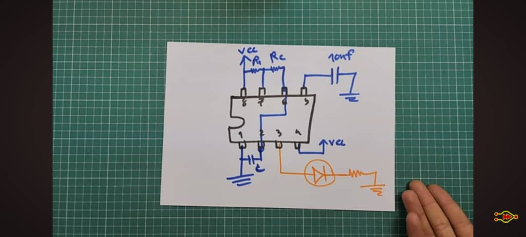
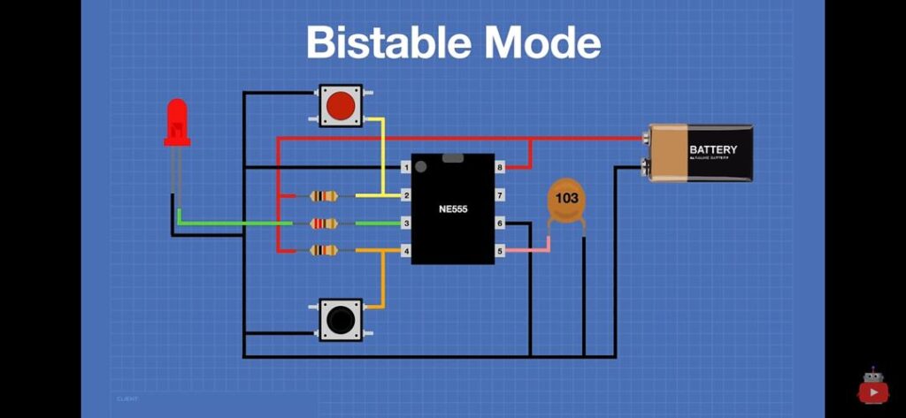
2. Bistable Mode – Flip-Flop Using NE555
Purpose:
To create a circuit that stays ON or OFF until a button is pressed — perfect for making toggle switches or memory elements.
Components Required:
NE555 Timer IC
2 Push Buttons (Red = Set, Black = Reset)
LED
3 Resistors
Capacitor (103 = 10nF)
9V Battery
Working Principle:
The bistable mode has two stable states
• ON: LED remains ON after pressing the SET button
• OFF: LED remains OFF after pressing the RESET button
This behavior mimics a flip-flop, where the state only changes when an external input (button press) occurs.
Pin Connections:
| PIN | FUNCTION | CONNECTION |
| 1 | GND | Battery -ve |
| 8 | VCC | Battery +ve |
| 3 | Output | Connected to LED |
| 2 | Trigger | Connected to SET button (Red) |
| 6 | Threshold | Connected to RESET button (Black) |
| 4 | Reset | Tied to VCC (disables auto-reset) |
| 5 | Control Voltage | Connected to 10nF capacitor to GND |
| 7 | Discharge | Not used |
Operation:
• Pressing SET (Red): Sends LOW to Pin 2 → Output goes HIGH → LED turns ON
• Pressing RESET (Black): Sends LOW to Pin 6 → Output goes LOW → LED turns OFF
This simple behavior demonstrates how a 555 timer can function as a manual switch with memory
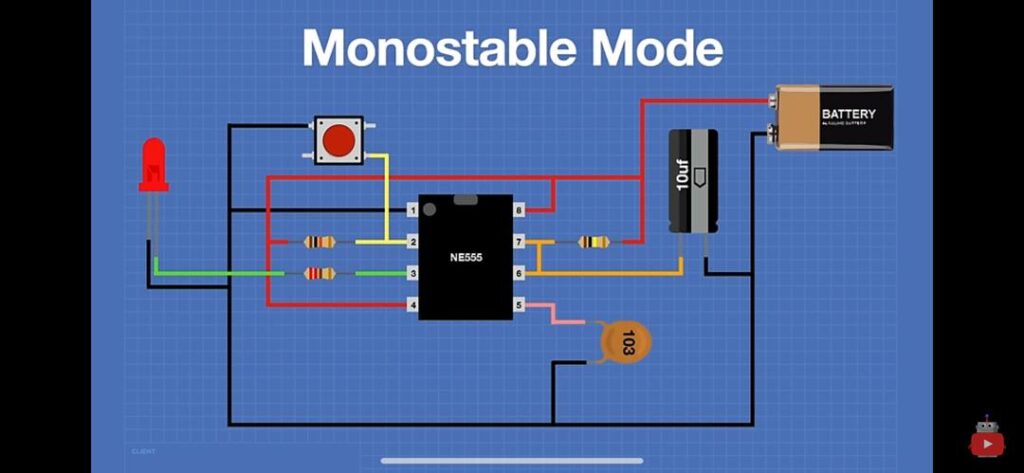
3. Monostable Mode – One-Shot Timer Using NE555
Purpose:
To turn ON an LED for a brief, specific duration when a button is pressed — commonly used in buzzers, timers, and alarms.
Components Used:
• NE555 Timer IC
• Push Button
• Capacitor (10µF)
• Resistor (10kΩ = 103)
• LED
• 9V Battery
Working Principle:
The monostable mode has one stable state (OFF). When triggered, the output goes HIGH temporarily, then returns to LOW automatically.
1. Idle: Output is LOW (LED OFF)
2. Button Pressed: LOW on Pin 2 triggers the timer → Output goes HIGH (LED ON)
3. After Delay: Capacitor charges → Output returns to LOW (LED OFF)
Time Delay Formula:
T ≈ 1.1 × R × C
Where:
T is the time delay in seconds
R is the resistance in ohms (Ω)
C is the capacitance in farads (F)
Example:
If R = 10 kΩ and C = 10 µF:
T ≈ 1.1 × 10,000 × 0.00001 = 0.11 seconds
Pin Connections:
| PIN | FUNCTION | CONNECTION |
| 1 | GND | Battery -ve |
| 2 | Trigger | Push button → GND |
| 3 | Output | Connected to LED (with current-limiting resistor) |
| 4 | Reset | Tied to VCC (to prevent unwanted resets) |
| 5 | Control Voltage | Optional capacitor (10nF) to GND |
| 6 | Threshold | Connected to Pin 7 |
| 7 | Discharge | Connected to capacitor and resistor |
| 8 | VCC | Battery +ve |
Conclusion:
These three simple NE555 circuits show how versatile the timer IC can be:
Bistable Mode is perfect for toggle switches and memory circuits.
Monostable Mode is ideal for timed outputs and one-shot activations.
Astable Mode is best for generating continuous pulses, such as blinking LEDs, clock signals, and tone generation.
These are beginner-friendly projects to learn about timing, switching, and digital logic using a single IC — making them great for workshops, exhibitions, or practical classroom demos.